Lagrangian Illumination for AMOR
Sufficient illumination of specimens is critical for AMOR to automatically localize and move specimens in the desired orientation. During development of AMOR, the standard illumination was hitherto a combination of a fiber-optics ring-light from above and two opposite sidewardly oriented arms of a swan-neck fiber optics illumination. Using crossed polarizing filters disturbing reflections and shadow generation could be reduced. However, during operation the geometry of the illumination proved not ideal, leading to unfavorable incident angles of the light when the stage attained strong tilting. Such situations caused unfavorable light loss due to the local geometry of the slide holder or poor illumination on the opposite side of the specimens leading to malfunction of the automatic orientation. In order to avoid such difficulties, a bright LED illumination was designed having parallel rows of poer-LEDs mounted directly on the moving slide holder and at close distances to the specimens. With this geometry the light source moves and tilts in the same coordinate system as the stage, for which the term "Lagrangian illumination" is coined here. The term Lagrangian is often applied in fluid dynamics for study approaches, where the observer (in our case the light) moves together with the local particle (the microfossil) under consideration, in contrast to Eulerian movements, where the observer (light source) remains fixed, while the observed particle (microfossil) passes by. The Lagrangian setting has the consequence, that the illumination of the particle remains constant, regardless of the movement of the stage.
More info under http://micropal-basel.unibas.ch/Research/MORPHCOL/SUPPL_22.pdf
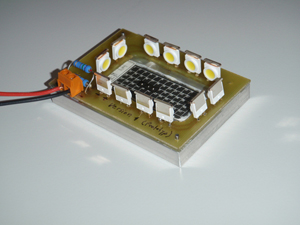
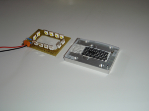
LEDs are mounted on an electronic circuit plate around the slide in proximity to the specimens. |
Metal base plate holding the multi-cellular slide (right) and electronic circuit with the LEDs (left) separated. When in operation, the two units must be insulated from each other. |
|
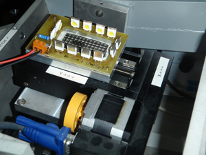
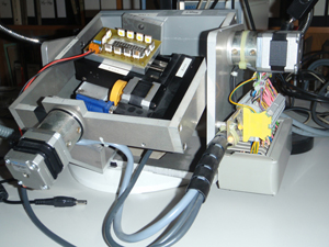
The illumination mounted on the tilting stage. |
Illumination angles relative to the specimens remain independent from the tilting position of the stage. |